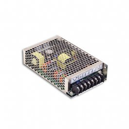
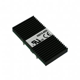
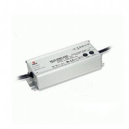
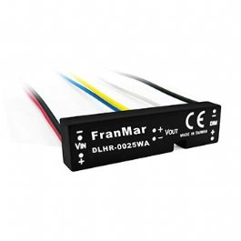

Power Supply with Special Modification

Engineering Challenges in Custom Power Supplies: FranMar’s Special Modification Technical Guide

Introduction: The Engineering Gap Between Standard and Full Custom
In the development cycles of Industrial Automation and Medical Devices, power supply specifications are often the last to be finalized but among the most difficult to adjust quickly. Project teams typically face a critical engineering and procurement dilemma:
  • Standard Off-The-Shelf (COTS): Pre-certified to global standards (UL/TÜV/CE/IEC), offering short lead times and low Minimum Order Quantities (MOQs). However, the nominal output voltage, connector types, and cable assembly specs rarely align perfectly with proprietary system requirements.
  • Full Custom Design: Delivers 100% precise specification compliance but demands steep upfront Tooling and Non-Recurring Engineering (NRE) fees, a grueling 6-to-12-month regulatory certification cycle, and high mass-production MOQs often exceeding tens of thousands of units.
FranMar International Inc. bridges this engineering gap through our Special Modification Power Supply approach. By utilizing a pre-certified, field-proven baseline architecture, our engineers implement targeted circuit tuning, mechanical enclosure alterations, or custom cable integrations. This meets client-specific requirements without triggering a costly and lengthy full re-certification cycle.

Section 1: Technical Foundation — Engineering Boundaries of Special Modification
1.1 Output Voltage Adjustment
In standard switching mode power supply (SMPS) architectures, the output voltage is regulated by a voltage divider network within the feedback loop. Without altering the primary power topology (such as LLC Resonant, Flyback, or Forward), FranMar’s engineering team can precisely calibrate the output voltage through three primary methods:
  1. Modifying the Voltage Divider Ratio across the optocoupler feedback loop.
  2. Adjusting the Reference Resistor Values peripheral to the TL431 or equivalent shunt regulator ICs.
  3. Fine-tuning the Transformer Turns Ratio to expand the stable voltage adjustment window.
Post-modification, the engineering team conducts comprehensive electrical validation—including load regulation, line regulation, and peak-to-peak ripple & noise measurements—to guarantee output stability remains within the safe margins of the original regulatory submission.
1.2 Transposition of Safety Regulations
This is one of FranMar's core technical competencies. Under standards such as IEC/UL 62368-1 (ITE/Industrial) and IEC 60601-1 (Medical), any structural or electrical deviation requires a formal change impact analysis to determine whether it fits within the bounds of the original Test Report.
FranMar utilizes a standardized compliance process:
  • Change Impact Analysis: Identifying how the special modifications (voltage shift, connector type, wire gauge cross-sectional area) impact critical safety tests like Dielectric Strength (Hi-Pot), Leakage Current, and Temperature Rise.
  • Boundary Verification: Confirming that the modified design ratings remain within the ultimate boundaries defined by the original CB Report or UL File.
  • Regulatory Documentation Update: If changes exceed internal document limits, FranMar's compliance team prepares technical variance reports to secure a Delta Certification from international agencies (UL, TÜV SÜD, SGS) instead of starting a full re-test, saving considerable time and budget.
Certification Metrics Full Re-Test / Full Certification Delta Certification (Change Report)
Timeline 3–12 Months 2–6 Weeks
Estimated Cost USD 15,000 – 50,000+ USD 3,000 – 8,000
1.3 Special Connector & Cable Assembly Integration
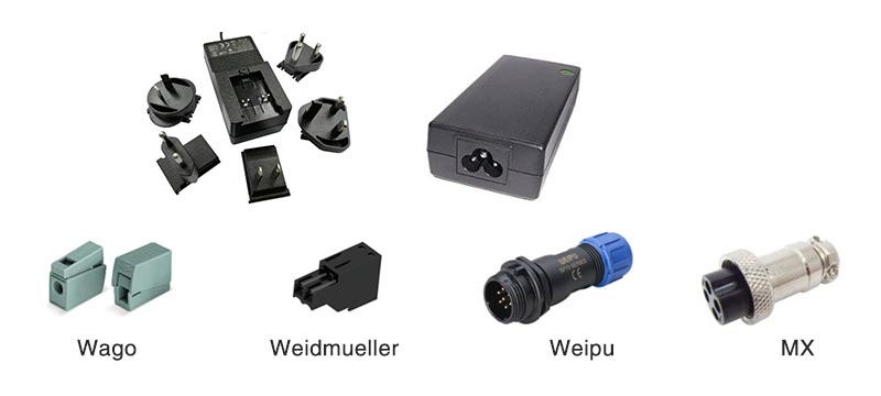
When a system demands integration with application-specific industrial or medical connectors (e.g., Molex Micro-Fit series, Hirose HR series, Weipu IP series), FranMar performs all crimping, soldering, and assembly pre-shipment. Every production batch undergoes strict quality control:
  • Continuity Test: Ensuring zero open or short circuits across all pins.
  • Impedance Measurement: Preventing excessive voltage drops caused by overly long wire runs or insufficient wire gauge (AWG).
  • Pull Force Test: Verifying crimp mechanical integrity against connector datasheet standards.
This one-stop integration eliminates the shared liability boundaries and yield losses commonly found when outsourcing secondary cable processing to third-party assembly houses.

Section 2: Engineering Case Studies

Case 1: Medical USB PD Power Supply — Locking Mechanism Design
  • Technical Background: The client’s clinical medical equipment required USB Power Delivery (USB PD Rev. 3.1) capability, relying on a PD Controller IC to handle power negotiation with the sink device. However, standard USB Type-C connectors offer a retention force of only 5–15 N. In fast-paced medical cart environments, accidental cable tugs can easily unplug the cord, causing data loss or power interruption during critical operations.
  • FranMar Engineering Solution:
    • Selected a medical-grade baseline architecture compliant with IEC 60601-1 2×MOPP (Means of Patient Protection) isolation.
    • Engineered a custom USB PD connector module equipped with a mechanical screw-locking mechanism, upgrading cable retention force to ≥ 45 N to prevent accidental disconnection.
    • Validated the full assembly under IEC 60601-1 for thermal limits and leakage current (< 100 µA to ground).
  • Outcome: The design achieved full compliance via Delta Certification, skipping the full re-certification process. This cut the regulatory timeline by roughly 60% while eliminating critical disconnection risks in clinical settings.
Case 2: Heavy Industrial Equipment — Screw Terminal Retrofitting
  • Technical Background: A heavy machinery client operated in conditions governed by IEC 60068-2-6 (Vibration Test Fc), featuring continuous vibrations of 10–55 Hz at 1.5 g acceleration. Standard plug-in connectors (like typical Molex or JST headers) experienced contact resistance drift under prolonged vibration, leading to output voltage instability, terminal oxidation, and potential safety hazards.
  • FranMar Engineering Solution:
    • Redesigned the power output layout from a friction-fit plug to a heavy-duty Screw Terminal block compliant with UL 508A, establishing a torque specification of 0.5–0.6 N·m.
    • Utilized tin-plated copper bus bars for the contact interfaces, keeping contact resistance at ≤ 5 mΩ (fully compliant with IEC 60999-1).
    • Selected terminal housings rated for a mechanical endurance of ≥ 500 mating cycles per IEC 61984/IEC 60947-1.
  • Outcome: Following deployment, field failure rates tied to loose connections or oxidized terminals dropped to zero, significantly boosting the system's overall MTBF. This modified configuration has now been adopted as the standard design footprint for the client's high-vibration product lines.
Case 3: High-End Outdoor Telecom & Base Stations — Waterproof Connector Integration
  • Technical Background: The client's next-generation outdoor 5G base stations and microwave telecom equipment were deployed in coastal areas, exposing them to salt spray corrosion, wind-induced vibration, and continuous UV exposure. Standard power terminal blocks lacked adequate ingress protection. Relying on field technicians to manually wire assemblies outdoors carried a high risk of moisture entry via capillary action, causing premature short circuits. The application strictly demanded certified IP68 waterproof performance.
  • FranMar Engineering Solution:
    • Precision Connector Integration: Tailored the power supply enclosure to seamlessly integrate premium outdoor circular connectors (such as Hirose HR series or Weipu IP-rated series) pre-shipment. These connectors feature distinct push-pull or bayonet three-step locking mechanism alongside weather-resistant polymer housings.
    • Factory-Level Validation: Assembled the components strictly according to manufacturer assembly specifications, and conducted 100% factory insulation resistance and dielectric strength testing on the finalized harness junctions.
  • Outcome: The client successfully moved away from complex, error-prone manual outdoor wiring, improving field installation efficiency by 70%. The power system passed rigorous accelerated weathering and salt spray testing, enabling smooth global deployment across extreme environments.
Section 3: Product Lines Supporting Special Modification
Product Category Primary Safety Standards Common Modification Options
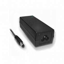
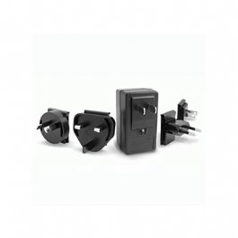
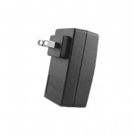
Industrial & Medical AC-DC Adapters UL 62368-1, IEC 62368-1, IEC 60601-1 Output voltage fine-tuning, specialized connector integration, custom cord lengths.
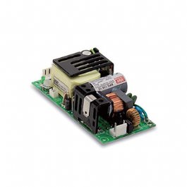
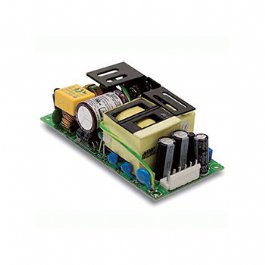
Open Frame Power Supplies UL 62368-1, IEC 62368-1 Alternative PCB headers, extended output voltage capabilities.
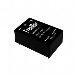
DC-DC Converters UL 62368-1, IEC 62368-1, IEC 60601-1 Precise output voltage calibration.
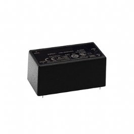
PCB Mount / Embedded Power IEC 62368-1, UL 60950-1 Custom pinout configurations, voltage modifications.
USB PD / GaN Chargers IEC 62368-1, USB PD Rev. 3.1 Screw-locking Type-C terminals, multi-port dynamic allocation layouts, modified enclosures.
Section 4: Technical FAQ
Q1: Does a Special Modification require full safety re-submission and testing?
A1: In most cases, no. Because FranMar’s modifications start from a pre-certified baseline power supply and keep circuit alterations strictly within controlled boundaries, they typically qualify for a Delta Certification (Change Report) with agencies like UL, TÜV SÜD, or SGS, rather than a full re-test. Whether your project requires a Delta Certification or simple internal document filing depends entirely on the nature of the shift. Our engineering team provides a clear assessment during the initial feasibility review.

Q2: What is the Minimum Order Quantity (MOQ) for modified units?
A2: The MOQ varies based on the technical complexity of the modifications. Projects that utilize existing mold adjustments (such as adjusting the output voltage or swapping out wire harnesses/connectors) have an MOQ that is significantly lower than the industry standard for a full custom design. Every project is assessed case-by-case; please provide your specific connector part numbers, cable specs, and target voltage to receive a precise quote.

Q3: What are the typical lead times for samples and mass production?
A3:
  • Technical Feasibility Assessment: Completed within 5 business days upon receiving your comprehensive specifications (voltage, current, connector part numbers, and cable length).
  • Engineering Samples: Typically ready within 2–4 weeks, depending on the exact complexity of the modification.
  • Mass Production: Because the process bypasses new tooling development and full certification wait times, mass production lead times are significantly shorter and more predictable than full-custom alternatives.
Official Product Portfolio: [FranMar Product Center]
Technical Inquiry & Project Quotation: [FranMar Contact Us]